BENDIX BW2726 User Manual
Browse online or download User Manual for Unknown BENDIX BW2726. BENDIX BW2726 User's Manual
- Page / 40
- Table of contents
- TROUBLESHOOTING
- BOOKMARKS
- SD‑13‑47672 1
- WARNING! PLEASE READ AND 2
- FOLLOW THESE INSTRUCTIONS TO 2
- 3. ANTILOCK BRAKE SYSTEM 3
- (ABS) OPERATION 3
- 4. BENDIX 4
- TRAILER ROLL STABILITY 4
- PROGRAM (TRSP 4
- ) OPERATION 4
- 5. COMPONENTS 5
- 6. MOUNTING 7
- 7. PIGTAIL WIRING HARNESSES 7
- 8. ABS INDICATOR LAMP 8
- 9. BENDIX 8
- SPEED SENSORS 8
- 12. AUXILIARY I/O 9
- Trailer ABS Indicator Lamp 10
- Odometer 10
- Trip Counter 10
- Service Interval 10
- 20. BLINK CODE DIAGNOSTICS 11
- 17. NON‑STANDARD TIRE SIZE 11
- 18. DIAGNOSTIC TROUBLE 11
- CODE DETECTION 11
- 19. PARTIAL ABS SHUTDOWN 11
- 21. AUXILIARY FEATURES 12
- (DTCs) (continued) 14
- Troubleshooting 20
- Trailer Information Module 21
- LEAKAGE AND OPERATIONAL TESTS 23
- ABS WIRING 25
- TABS-6ADVANCEDMCMODULEECU 26
- 0 Degree Mounting Orientation 27
- Left - “Road-Side” 31
- Right - “Curb-Side” 31
- Troubleshooting: Flowcharts 34
- ABS INDICATOR LAMP CIRCUITRY 36
- POWER SUPPLY 37
- WHEEL SPEED SENSORS (WSS) 38
- K987654Vxx 40
Summary of Contents
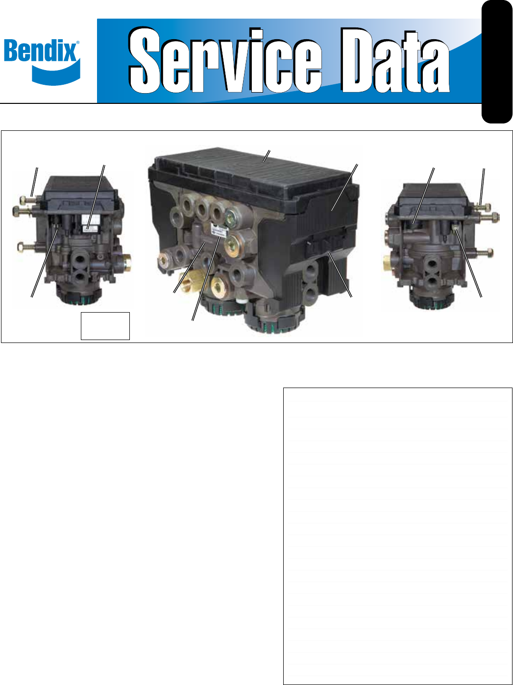
1Bendix® TABS‑6™ Advanced Multi‑Channel Trailer ABS ModuleFIGURE 1 - BENDIX® TABS -6™ ADVANCED MULTI-CHANNEL MODULE (BENDIX TABS-6 ADV MC)1. INTRODUCT
1013. BENDIX® ABS FLEX™ PROGRAMThe BendixABS Flex program usesAuxiliary DesignLanguage(ADL)toallowcustomizedauxiliaryfunctionstobe car
1117. NON‑STANDARD TIRE SIZEThe Bendix® TABS‑6™ Adv MC module allows for tire rolling radius and tone ring tooth count parameters to be set for the a
12Wait until after the modulator chuff test before activating thebrakelightpower.Alternatively,waitve(5)seconds.Note: If certain Diagnostic
1322. DIAGNOSTIC TROUBLE CODES (DTCS)1st Digit2nd DigitDiagnostic Code DescriptionPossible Causes / Repair InformationJ1587 (SID/FMI)J1939(SPN/FMI)1
141st Digit2nd DigitDiagnostic Code DescriptionPossible Causes / Repair InformationJ1587 (SID/FMI)J1939(SPN/FMI)Trailer Power6 1 Over-voltagePowerSup
15Diagnostic Trouble Codes (DTCs) (continued)1st Digit2nd DigitDiagnostic Code DescriptionPossible Causes / Repair InformationJ1587 (SID/FMI)J1939(SPN
16Diagnostic Trouble Codes (DTCs) (continued)1st Digit2nd DigitDiagnostic Code DescriptionPossible Causes / Repair InformationJ1587 (SID/FMI)J1939(SPN
171st Digit2nd DigitDiagnostic Code DescriptionPossible Causes / Repair InformationJ1587 (SID/FMI)J1939(SPN/FMI)TABS‑6 Adv MC module10 1TABS‑6 Adv MC
181st Digit2nd DigitDiagnostic Code DescriptionPossible Causes / Repair InformationJ1587 (SID/FMI)J1939(SPN/FMI)AuxiliaryDesignLanguage(ADL)&
191st Digit2nd DigitDiagnostic Code DescriptionPossible Causes / Repair InformationJ1587 (SID/FMI)J1939(SPN/FMI)11 8AuxiliaryElectricalError#4• Cle
2● Awidevarietyofelectricalinputs/outputs(I/Os)allowthe customer to program auxiliary functions such as: automatic LiftAxle Control (LAC)
20USING HAND‑HELD ORPC‑BASED DIAGNOSTICSTroubleshooting and Diagnostic TroubleCode (DTC)clearing,aswellasbeginningareconguration,mayalso
21How the Bendix® TRDU™ Tool OperatesWhentheTRDUtoolispluggedintotheadapter—andtheadapter/TRDUtoolisinstalledbetweenthetrailerconne
22To better serve you, please record the following information before you call the Bendix Tech Team, or include this information in your e‑mail:• Ben
231. TheTABS-6AdvMCmoduleshallbeinstalledwiththefollowingconsiderations(seeFigures16through18):5°5°VERTICAL ORIENTATION (ROLL ANGLE)M
24FIGURE 19 ‑ WHEEL SPEED SENSOR INSTALLATIONP22P21P21P220° Mounting Orientation 180° Mounting OrientationVehicle Driving DirectionVehicle Driving Dir
25• Mechanical Load Sensor Test (Mechanical Spring Ride): The test has the user verify the expected measurement of the spring deectionsensor.
26FIGURE 20 ‑ BENDIX® TABS -6™ ADV MC MODULE ELECTRICAL SCHEMATIC - 2S/2MFIGURE 21 ‑ BENDIX TABS-6 ADV MC MODULE ELECTRICAL SCHEMATIC - 4S/2MTrouble
27FIGURE 22 - BENDIX® TABS -6™ ADV MC MODULE - 2S/2M SIDE CONTROL (0 DEGREE) ABS ELECTRICAL & AIR SYSTEMFIGURE 23 - BENDIX TABS-6 ADV MC MODULE -
284S/2M - SIDE CONTROL - Fixed Axles0 Degree Mounting OrientationIgnition PowerTrailer Chassis HarnessBendix®TABS-6™Advanced Multi-ChannelBendix® SR-5
29FIGURE 26 - BENDIX® TABS -6™ ADV MC MODULE - TYPICAL 4S/2M AXLE CONTROL ABS ELECTRICAL & AIR SYSTEMFIGURE 27 - BENDIX TABS-6 ADV MC MODULE - 4S/
33. ANTILOCK BRAKE SYSTEM (ABS) OPERATIONThe Bendix® TABS‑6™ Adv MC module uses wheel speed sensors,modulatorrelayvalves(MRVs);andanECUtoop
30FIGURE 28 - 4S/2M SIDE CONTROL (0 DEGREE) WITH FRONT LIFT AXLE, ABS ELECTRICAL & AIR SYSTEMFIGURE 29 - 4S/2M SIDE CONTROL (0 DEGREE) WITH REAR L
31FIGURE 30 - 4S/2M SIDE CONTROL (180 DEGREE) WITH FRONT LIFT AXLE, ABS ELECTRICAL & AIR SYSTEMFIGURE 31 - 4S/2M SIDE CONTROL (180 DEGREE) WITH RE
324S/2M - AXLE CONTROL - Front Lift Axle180 Degree Mounting OrientationA Brake Lamp PowerB Ignition PowerC NCD Indicator LampE GroundIgnition Power
33FIGURE 34 - BENDIX® TABS -6™ ADV MC MODULE - TYPICAL 4S/2M SYSTEM WITH FRONT LIFT AXLEFIGURE 35 - BENDIX TABS-6 ADV MC MODULE - 4S/2M AXLE CONTROL S
34SectionA:(Power-UpSequence)Trailer‑Mounted ABS Indicator Lamp ...Page 34SectionB:(Power-UpSequence)Dash‑Mounted ABS Indicator La
35SECTION B: (POWER‑UP SEQUENCE)DASH‑MOUNTED ABS INDICATOR LAMPObservethedash-mountedTrailerABSIndicatorLampatPower-UpVerifythataPLCtraile
36SECTION C: TROUBLESHOOTING THE TRAILER‑MOUNTEDABS INDICATOR LAMP CIRCUITRYLookingintotheBendix® TABS‑6™ Adv MC Module 7‑pin Connector Pigtail Har
37Measure the loaded voltage across a type 1157brakelightbulb.LookingintoTABS-6Advanced MC Module 7‑pin Connector Pigtail Harness Measure:Igniti
38S‑D and S‑F Sensor(SeeFigure19forUsage.)S‑C and S‑E Sensor(SeeFigure19forUsage.)SECTION E: TROUBLESHOOTING THEBENDIX® WS‑24™ WHEEL SPEED SEN
39SECTION F: TROUBLESHOOTING THELOAD SENSOR (OUT‑OF‑RANGE CONDITION)(Note: The indicator lamp for this condition is illuminated only after the vehicl
44. BENDIX® TRAILER ROLL STABILITY PROGRAM (TRSP®) OPERATION WARNING! During a Bendix® TRSP® system intervention, the vehicle automatically decelerat
40ECU Part Number LabelThe external part number label is located above the control port of the module. If this label is not readable for any reason,
55. COMPONENTSInstallations of the TABS‑6 Adv MC module use the following components:Internal:• Electronic Control Unit (ECU): TheECUmonitorsthe
6• Pigtail Wiring Harness: A power pigtail harness is required.Auxiliaryharnessesareavailable,asneeded.See Figure 6.• Lift Axle Sensing:
7deection.Theconnection tothe ElectronicControlUnit(ECU)isviatheauxiliary12-pinconnector.See Figure 6.6. MOUNTINGFrame (Chassis) Mou
8CAUTION: Correct wheel speed sensor installation is necessary for optimal ABS operation.NOTE:Ifthetrailerisequippedwithaliftaxlethatwill
910. SAE J2497 (PLC) DIAGNOSTIC LINKAll newer towed vehicles transmit a signal over the power linetothetowingvehicleABSECU.Thesignal,using
Related products and manuals for Unknown BENDIX BW2726
 (8 pages)
 (1 pages)
(1 pages)
(1 pages)
 (1 pages)
(1 pages)
(1 pages)
(1 pages)
(32 pages)
(1 pages)
(1 pages)
(4 pages)
(1 pages)
(1 pages)
(1 pages)
(1 pages)
(1 pages)
(32 pages)
(1 pages)
(1 pages)
(4 pages)
 (4 pages)
(12 pages)
(2 pages)
(1 pages)
(42 pages)
(2 pages)
(1 pages)
(2 pages)
(4 pages)
(12 pages)
(2 pages)
(1 pages)
(42 pages)
(2 pages)
(1 pages)
(2 pages)
© 2020, manymanuals.com. All rights reserved. | 0.028 s |
 Manymanuals.com
 Manymanuals.de
 Manymanuals.fr
 Manymanuals.it
 Manymanuals.pl
 Manymanuals.cz
 Manymanuals.es
 Manymanuals-pt.com
Comments to this Manuals