BENDIX BW1662 User Manual

Browse online or download User Manual for Unknown BENDIX BW1662. BENDIX BW1662 User's Manual

  • Download
  • Add to my manuals
  • Print
  • Page
    / 4
  • Table of contents
  • BOOKMARKS
  • Rated. / 5. Based on customer reviews
Page view 0
1
®
SD-13-4754
Bendix
®
WS-20
AntiLock Wheel Speed Sensor
FIGURE 1 - WS-20
ANTILOCK WHEEL SPEED SENSORS
coil. Each time an exciter tooth and its adjacent space move
past the tip of the sensor, an AC voltage "cycle" is generated.
The number of AC cycles per revolution of the vehicle's wheel
depends on the number of teeth in the exciter, which is
programmed into the antilock controller. Using the
programmed data, the controller can calculate "vehicle
speed" by analyzing the frequency of AC cycles sent by the
speed sensor. (The frequency of AC cycles is directly
proportional to wheel speed.)
AC voltage is also proportional to speed, but voltage is not
used to determine speed. It is only an indication of AC signal
strength. The amount of AC voltage generated by a specific
speed sensor depends on the distance, or "gap," between
the tip of the sensor and the surface of the exciter. Voltage
increases as the sensor gap decreases.
The WS-20
wheel speed sensor is installed in a mounting
block that is affixed to the axle housing. (See Figure 2.) A
spring loaded retainer bushing provides a friction fit between
the mounting block bore and the WS-20
sensor. The friction
fit allows the WS-20
sensor to "slide" back and forth under
force but to retain its position when force is removed. This
DESCRIPTION
The WS-20
wheel speed sensor is an electromagnetic
device used to obtain vehicle speed information for an antilock
controller. When the wheel rotates, the sensor and an exciter
(e.g. rotor or tone wheel) generate a simple AC signal. This
signal is sent to the controller, which analyzes the data and
commands the antilock system accordingly.
Specifically, the speed sensor consists of a coil, pole piece,
and magnet. The exciter is a steel ring or gear-like device
that has regularly spaced high and low spots called "teeth."
The sensor is mounted in a fixed position, while the exciter
is installed on a rotating member so that its "teeth" move, in
close proximity, past the tip of the sensor.
The WS-20
wheel speed sensor is available in both straight
and right angle versions, to accommodate axle/wheel space
limitations. (See Figure 1.)
OPERATION
The sensor's magnet and pole piece form a magnetic field.
As an exciter tooth passes by the sensor, the magnetic
field is altered, which generates AC voltage in the sensor
PACKARD 2 PIN
CONNECTOR
90° WS-20
SENSOR
DEUTSCH 2 PIN
CONNECTOR
STRAIGHT WS-20
SENSOR
Page view 0
1 2 3 4

Summary of Contents

Page 1 - AntiLock Wheel Speed Sensor

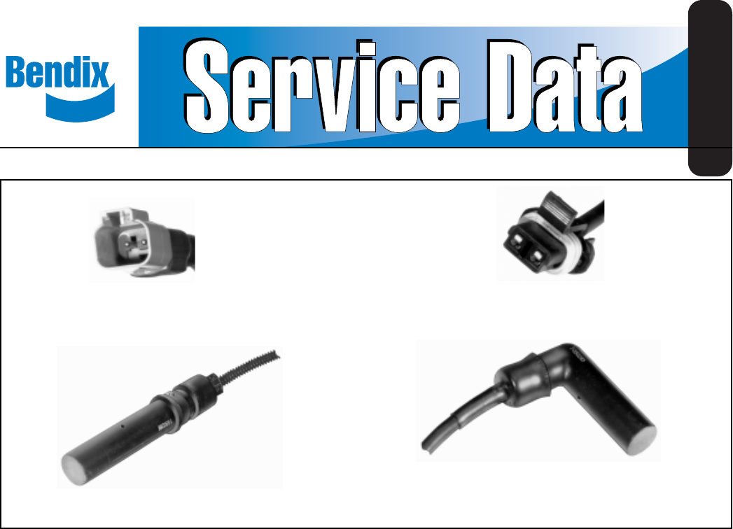
1®SD-13-4754Bendix® WS-20™ AntiLock Wheel Speed SensorFIGURE 1 - WS-20™ ANTILOCK WHEEL SPEED SENSORScoil. Each time an exciter tooth and its adjacent

Page 2 - PEAK TO PEAK

2ANTILOCK CONTROLLER& RELAYWS-20™ SPEED SENSORSEXCITERSFRONT WHEELREAR WHEELSfeature allows the WS-20™ sensor to "self adjust" after ith

Page 3 - SENSOR INSTALLATION

3FIGURE 4 - WS-20™ WHEEL SPEED SENSOR INSTALLATIONall reservoirs before beginning ANY work on thevehicle. If the vehicle is equipped with an AD-IS™ai

Page 4 - OPERATIONAL TESTING

43. Reconnect the connector to the sensor lead by pluggingit into the appropriate socket on the pigtail harness, andpushing until the lock tab snaps i

Comments to this Manuals

No comments